Reinforced Concrete Design: All Epoxies are not created equal!

Tags

, , , , , , , , , , , ,

Epoxying steel rods and bolts is very common in construction projects, especially when attaching new structure to existing buildings.  Over 90% of our projects include the use of epoxies for fastening steel base plates, hold-downs, connecting new foundations to existing concrete structure, etc.  We spend a lot of time choosing the right epoxy for the job and it is important to understand that not all epoxy is created equal.

The first thing we try and do is choose an epoxy that is readily available at local distributors.  Local lumber yards and steel reinforcing distributors may not carry all brands.  We typically specify Simpson or Hilti products because they are easy for contractors to source here in the Denver Metropolitan area and are typically available anywhere.  These companies provide endless information about their products and they have software and engineers on staff to answer any questions.

Next we choose the right epoxy for the application.  The manufacturer will provide technical information about the adhesive.  Catalogs and online tables give information about shear and tension capacities based on the type of rod material and building material (such as concrete, brick, masonry, etc.).  Edge distance and spacing between rods is also very important and is incorporated in the design strength.

Lastly, we live in a climate with varying temperatures here in Colorado.  We do a lot of work in the mountains and epoxies that can cure in lower temperatures are important.  We don’t always know when construction will occur and we try and choose an epoxy for a variety of temperatures when possible.  But we also have to rely on the installer to know the limitations of the epoxy adhesive that they are working with.  Using an epoxy in extreme temperatures may severely compromise it’s strength.

In conclusion, always follow your engineer’s recommendations.  This may seem trivial, but 60-70 percent of the time we see a different epoxy installed from what was specified on our plans.  Also always know the limitations of the epoxy that you are installing.  This information is typically provided with the adhesive and is also readily available online.  Not all epoxies are created equal and specific adhesives are chosen for their properties and the type of design application.

If you have any other questions about epoxy, how it is installed and if it is suitable for your construction project, contact us!  Read more about Reinforced Concrete Design and other Building Projects on our Blog.
 

Structural Steel and Architectural Design

Tags

, , , , , , , , , , ,

Whenever there is an option to combine structure with architectural design, structural engineers get excited!  Typically our structure is hidden within walls or covered by drywall.  In our opinion there is nothing more elegant than exposed structure, especially structural steel.  So naturally we jumped at the chance to used exposed structural steel cables in our design of the Cargil Residence with Rodwin Architecture.

Cargill_2-1-13_WHITE_NORTHEAST

Most conventional wood framed buildings take advantage of continuous foundation walls, sheathed stud walls and steel hold-downs to brace the building against lateral loading and overturning, (see our post on “Seismic and Wind Resistant Construction“).  When the building cantilevers off its foundation or is supported by independent vertical columns, a different system must be engineered to brace the building against lateral forces and resist overturning.

Cargill_2-1-13_WHITE_SOUTHEAST

The lateral force resistance system at the end of this building consists of steel tension cables fastened between vertical wood columns.  Steel brackets at both the top and the bottom of the wood columns were carefully detailed to connect the cables to the wood columns and transfer the vertical and horizontal forces from the floor diaphragm above to the foundation below.  Below each column is an individual concrete pedestal and footing which supports the vertically loads and resists overturning of the structure.

Model1

All successful buildings are the creation of a good design team.  We were fortunate to work with Rodwin Architecture and SkyCastle Homes on this project.  Just because a design works on paper doesn’t mean it is feasible in the field.  We all worked hard on this project to meet the architectural objectives while at the same time meeting a tight budget and difficult site constraints.

If you have any other questions about how to build or design with wood, steel or concrete visit the Wood Framed Construction, Structural Steel and Reinforced Concrete categories of our blog.  Or if you have a difficult and intricate design problem, feel free to contact us.  We will help you determine a safe, economical and aesthetic solution.

Steel Construction: Adding New Roof-Top Units to an Exist.Steel Roof Structure

Tags

, , , , , , , , , , , , , ,

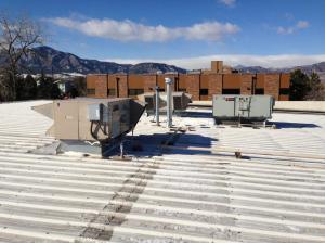
Often we are asked to evaluate an existing steel roof structure to determine if it can support new roof top units.  Tenants frequently remodel commercial spaces for their current needs and in many cases add new air make-up units, exhaust fans and HVAC units.  In the last month we were asked to evaluate two commercial spaces for new rooftop units.  One space was adding a commercial kitchen and needed new exhaust fans and an air make-up unit.  The other was a medical marijuana grow facility and needed new cooling units to counter all the extra heat they were experiencing from their lamps.

Roof Top Unit

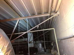
New roof top units can be large and heavy and typically bear on the existing roof structure.   Before examining the structure we contact the mechanical engineer working on the project to find out the size, weight and optimal location of the new units.  We then examine the existing roof structure to determine the size, spacing and span of the joists, location of bearing walls and girders and location of existing roof top units.  A typical commercial roof structure in our area is constructed with steel bar joists.  Most joists are tagged by the manufacturer, such as Vulcraft, who keep records of the type of joists they use on each of their projects.  However, we still take accurate measurements of the top and bottom flanges, the web members and the length of the joist.  We also try to observe each end and somewhere along the length of each joist potentially supporting a new unit.  This is important to make sure that all new and existing load can be adequately transferred to the supporting structure.

IMG_1985

Once the properties of the joists are known, we determine its capacity from the manufacturer and/or we model it based on its section properties.  This helps us determine the load carrying capacity of the steel joist.  Typically existing joists do not have a lot of extra load carrying capacity, especially if they are already supporting an existing rooftop unit.  Joists can be strengthened by welding steel rods and plates to the flanges, similar to how we would strengthen a steel beam (see blog post “How to Strengthen an Existing Support Beam“).  However this doesn’t result in large increases in capacity.  It is usually best to locate a new unit away from existing units and near an existing bearing wall or girder, limiting the amount of new load on the existing joists.

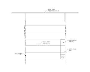
Rooftop Unit Plan

For example, last month we visited an existing tilt-up concrete building with steel bar roof joists for Blue Spruce Design and Construction.  They needed to put a new, large air make-up unit on the roof for their client Boulder Bridge House.  We quickly determined that the existing joists had no extra capacity for supporting a new unit along their length, however if the new unit was located near the end of the joist, there was sufficient shear capacity to transfer the load to the supporting steel beam.  We worked with the mechanical engineer to locate the new unit and reduce the amount structural revisions needed.

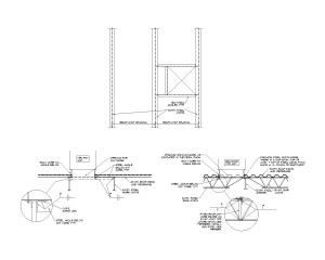
Rooftop Unit DETAIL

We then created details for the contractor illustrating how to modify the existing roof structure to support the new units.  New steel angles were added to support the metal decking at all new openings and below all edges of the new rooftop unit.  It was also important to adequately fasten the new unit to the roof structure below.  We live and work in an area with high winds.  Units that are not properly fastened experience movement, become damaged or cause damage to the structure and its inhabitants.

Examining an existing structure, determining its strength and capacity and modifying it accordingly is something we really enjoy.  It takes a strong understanding of structural design, but also a wealth of knowledge of building construction.  This is where many years of experience are important.  Lastly, I think one of the major reasons we enjoy this work is because it is never the same and requires a lot of problem solving.  Visit the Steel Construction section of our blog for more how to design with steel.

Architectural Design: Wide Open Spaces

Tags

, , , , ,

Residential Architecture and design is constantly changing!  I live in a home that was built during the late fifties and the way I sum up my house is: “There are a lot of walls and small rooms!”  Most of the homes I design now have no bearing walls.  They have large beams and columns and big open spaces.  They are big, dynamic and beautiful.  But what about a home like mine?  Can an existing home be remodeled to feel the same way?

schafferhouse_0007

When we began the “Shaffer Residence” remodel with ESA Architecture, the goal was large open spaces with no dropped beams.  The house was similar to mine, with many bearing walls and a ceiling that was only 8 feet.  We had to get creative and strengthen existing steel beams in place to carry new loads and remove bearing walls.  We also added new steel members and had to come up with out-of-box solutions for how to fasten new and existing members together and conceal their supports.

schafferhouse_0001

Another challenge was matching the existing floor depth.  The original floor was constructed with 2×8 joists, which had shrunk over time to a depth of 7″.  All new lumber had to be either engineered or dimensional lumber with a low moisture content to help eliminate shrinkage of new materials.  If new dimensional lumber with a high moisture content had been installed, it is likely that differential movement between the new and old sections of the house would have occurred.

schafferhouse_0009

Lastly, newer homes tend to have large openings in their exterior walls for more natural light, passive solar, dramatic views, etc.  The Shaffer residence faced south and had one of the best views in all of Boulder, CO.  It was important to the owner to open the building for more light and take advantage of the view.  They wanted to install a Nano door to allow the interior to extend out on the new deck, seamlessly.  This was a structural challenge and the foundation and wood framing had to be updated for the new large openings.  In addition, special consideration had to be taken to ensure that the house had enough lateral capacity to resist the strong wind forces in Boulder.

schafferhouse_0004Older homes can be remodeled to function and feel like a new home.  But as the owners and designers on this project can tell you, it will take patience, time and a good design and construction team to figure out how to combine the old with the new.  Almost every remodel that we have gotten involved with has had a surprise hidden behind its walls, but for us, that is part of the challenge.

Steel Construction: How to Strenghthen an Existing Support Beam

Tags

, , , , ,

Remodeling an older building to make it feel more open and spacious can be an arduous task.  Installing larger steel I-beams to support new additions can be costly and difficult to manoeuver into the existing structure.  In addition, how do you brace the building while removing existing members and adding new stronger ones?  Another option is to strengthen the existing steel beam.  It remains in place to support the existing structure and afterward it should have the capacity to support the new addition.

schafferhouse_0008In a remodel of a wood framed building we recently completed, the objective was to open the existing space as much as possible and to add new square footage to the upper level.  There was an existing steel I-beam that spanned over 25 feet and with the new addition it was going to receive additional load.  The beam’s capacity was currently maxed out and would become overstressed.

S530-Model

We increased the beam’s flexural capacity and reduced its deflection by welding steel rods and plates to the steel beam’s web and flanges.  The additional steel increased the beam’s Moment of Inertia (I), which decreased the beam’s deflection.  The additional steel also increased the Section Modulus (S) of the beam, increasing the flexural capacity.

Strengthening the existing steel beam was a perfect way to achieve the open space the client wanted and reduce the construction costs associated with bracing the building and adding a new deeper beam.  We were also fortunate to work with a skilled contractor (Tom Stanko) to make sure that the beam modifications were installed correctly.  To learn more about Steel Construction visit other posts on our blog or contact us to learn how you can modify steel members economically and efficiently.

Reinforced Concrete Construction: Bracing The Top of The Wall

foundationReinforced concrete foundation walls provide the support for the structure above, but they also must resist the lateral load from the adjacent soil, hydrostatic forces and surcharge.  It is expensive and unnecessary to design the foundation wall to resist the lateral loading solely, without using adjacent structure.  Concrete retaining walls are designed to resist lateral loading, but typically use large footings or tie-backs to resist overturning and sliding.

foundation2Some engineers prefer to brace the top of the wall and resist overturning with additional foundation structure, such as counterforts.  The benefits of this design are the ability to backfill the wall once the concrete has curred and the top of the wall doesn’t need to extend to the floor structure above.  The down side to counterforts is they are an additional structure and expense.  To work properly, they must be installed fairly often to provide enough dead load to resist overturning.

foundation1When possible, we prefer to brace the top of the wall with the adjacent floor structure.  This design takes advantage of the existing floor framing.  It is cost-effective and typically only requires additional nailing between the bottom of the joist and the sill plate and blocking where the joists are parallel to the foundation walls.  Our clients use temporary bracing if the walls need to be backfilled prior to the installation of the floor framing above.

We understand that architectural design and site conditions greatly effect the design of the foundation, but whenever possible we try to be economical with our foundation structure.  To learn more about concrete design visit the Reinforced Concrete Construction section of our blog.

Seismic and Wind Resistant Construction: How to Transfer Lateral Load from the Roof Framing to the Shear Wall Below

In wood framed construction, it is important to transfer lateral forces from the roof framing to the shear walls below.  This can easily be accomplished in a number of ways, but it is often overlooked at the job site.  In addition, this connection can be hard to observe once exterior sheathing or house-wrap is in place.  Lateral design is an important part of construction and building departments are starting to require lateral design calculations and are looking more carefully for hold-downs and other lateral connections at the site.  The purpose of this post is to show several options for how to connect the roof framing to the shear walls below and explain which methods are easier to identify in the field.

shear2At bearing walls, where rafters and trusses bear on exterior or interior shear walls, blocking is the most effective way of transferring lateral forces from the roof to the top plates.  We typically see one of three connections: 1. Extend the wall sheathing up past the top plates and fasten it to both the blocking and top plates with edge nailing, 2. Toe-nail the blocking to the top plates per the IRC code or engineers specifications, 3. Fasten the blocking to the top plates with angles, such as Simpson A35 ties.  We find that toe-nails and angles can easily be installed both during framing and after the house has been sheathed and wrapped.  Extending the exterior sheathing is a good option, but must be pre-planned and can not be inspected once house wrap has been installed.

shear2At gable end walls, the gable end truss must be fastened to the top plates below, to transfer the lateral forces.  Again, there are several ways to accomplish this: 1. Extend the sheathing from the gable end truss down to the top plates and fasten it with edge nailing, 2. Toe-nail the bottom chord of the gable end truss to the top plates per the IRC code or engineers specifications, 3. Fasten the bottom chord to the top plates with angles.  We typically specify angles between the bottom chord of truss and the top plates because they provide good lateral transfer and can be easily observed at the job site.  Extending sheathing and toe-nails can not be observed once the house wrap is installed.  Framers typically fasten the sheathing to the gable end truss on the ground, before lifting it into place, and it is hard to leave an extension at the bottom.

Most engineers will include typical details or sections illustrating how to transfer lateral forces from the roof framing to the shear walls below.  Discussing this connection with your engineer will help to reduce framing revisions.  Angles can usually be installed if sheathing extensions or toe-nails are not installed correctly.  This can be expensive, but may be more cost-effective than removing house wrap and siding.

Contact us with you have any further questions about shear transfer and visit the wood framed construction category of our blog for more about residential construction and lateral design.

Meeting Energy Efficiency Goals: Exterior Rigid Insulation

Dow SIS

Over the past decade, we have been involved in the design of hundreds of residential homes.  HERS ratings have been dropping and the efficiency of homes has been rising.  It can be a bit frustrating sometimes from the perspective of a Structural Engineer because we can not always play a big role in making a home energy-efficient.  We use engineered lumber, specify studs at 24″ on center and simplify design whenever possible to limit the use of unneeded resources.  But we are always looking to work with like minds and be more involved in the process of making a home more energy-efficient.

A couple of years ago, several of our clients asked us to explore using Structurally Insulated Sheathing instead of the traditional OSB exterior sheathing.  This panel can replace OSB, exterior rigid foam and house wrap.  These panels can be fastened directly to the outside face of the exterior stud wall.  The seams can than be taped and according to Dow, no additional house wrap is required.  They typically come in two different thicknesses, 1/2″ and 1″, with an R value of 3 and 5 respectively.

Our clients wanted to try this product because they were having trouble achieving the required/desired insulation in the exterior wall cavities.  They had already switched to a stud pacing of 24″ o.c., but with 2×6 studs, there is a limit to the maximum R value that can be achieved.  In addition, exterior rigid foam interrupts thermal bridging, (cold from conducting through adjacent wood products).

The product proved challenging from a structural and building perspective.  Our clients were frustrated with the ‘SIS’ panels because they were easily damaged at the site.  The installers punctured them and the panels de-laminated quickly.  All of our clients continued to use house wrap because they felt that simply taping the seams wasn’t equivalent.

From a structural perspective, the panels do not have the same capacity as OSB sheathing for resisting lateral shear.  The panels can be installed with both nails or staples, however staple installation tested better.  To increase lateral shear capacity, drywall can be glued and screwed on the inside face of the stud.  Manufacturers of these types of panels typically provide good spreadsheets illustrating values for these installations, however we were unable to find any testing on forces perpendicular to the wall, such as suction.

We found the biggest structural challenge was educating the installers.  Fasteners must penetrate the foam layer of the panel so that they adequately penetrate the wall stud.  This is easier said than done for 1″ thick panels fastened with staples.  In addition, framers who typically install OSB sheathing are not used to installing with staples. They would install the panels with nails, reducing the lateral capacity by approximately 30%, from a staple installation.  Adding additional fasteners did not seem like a viable option because the fasteners were already installed at 3″ o.c. and adding more fasteners compromised the integrity of the panel.  Our designs typically included more interior shear panels or required the installation of OSB sheathing at certain locations.

If you have used the ‘SIS’ panels or a similar product, we would like to hear your thoughts.  What were some of the successes and obstacles you encountered?

For more on green building or residential construction, visit our green building or wood framed construction categories of our blog.

Rammed Earth Co-Housing in South Africa

Rammed Earth Co-Housing

This winter we helped consult on a Rammed Earth Co-housing project in South Africa with Bryan Bowen Arcthitects.  The goal of the housing project will be to bridge traditionally segregated communites with environmentally friendly buildings.  How could we say no to getting involved with that?  Bryan has taken great care in designing simple, asthetic bulidings that are incorporated into the already existing permacultrure gardens, established by the owner of the project.  See more at their Bryan Bowen’s Facebook page.

Rammed Earth Construction

Rammed Earch is an interesting material to design with.  It is not a good choice for large modern buildings with large open areas, but is proving idea for the small buildings that Bryan is designing and building.  Convential construction materials are expensive and not readily available in remote South Africa.  Rammed earth can be made from the soil on hand with some basic testing and good quality control.

Rammed Earth in South Africa

What is also exciting about this project is that it is helping change the concept of a home.  Traditonally the homes in this area are built with Masonry or Concrete.  There is a perception that a home made from earth is not as good or that it is a progression backward.  Bryan is helping to change these perceptions and show people that beautiful homes can be built from earth and what is local.  He is also helping to strengthen the sense of community.  We are excited to work with him on a project that is making changes on many different levels.

Visit our Architectural Design and Green Building categories for more about design and innovation.

Snow Tubing at Winter Park Resort

New Winter Park Tubing Building

Winter Park Ski Resort is opening up a new Tubing Hill behind the Vintage Hotel.  We worked with Architect Rosemary Fivian and the Winter Park staff to come up with a design that is energy-efficient, dynamic and meets the needs of the resort, no matter the season!  We hope you come up this winter for a run down the new hill and cup of warm hot chocolate by the indoor/outdoor fireplace.  Rosie has several updates on the buildings progress on her blog.

This building is unique in that it has large open spaces, tall wood framed walls and windows that extend to the underside of the roof.  We worked with Winter Park, Rosie and Rosboro to design a Glu-lam roof structure that met both the structural and budget needs of the project.  We incorporated a new product call Rosboro X-beam.  X-beams are Glu-lam beams that are more conventional in size, matching Micro-lam beam sizes and cost about 30% less than Micro-lam beams.

We have specified Rosboro X-beam Glu-lam beams on several projects now.  They can be used instead of Micro-lam or LVL wood beams and have a similar structural capacity.  For those specifying X-beams in design, it is important to note that they are 24F-V4 and not equivalent structurally to Micro-lams in a multi-span application.  What this means is that the top laminations do not have the same flexural stress capacity as the bottom laminations.  This is important when the beam is used continuously in a multi-span application because the top of the beam will also experience tension.  This hasn’t been a limiting factor in the residential and light commercial projects where we have incorporated the X-beam in the design.  It is also important to note that the standard hole and notches that may be applied to the beam are slightly different from a Micro-lam.  Designers looking for a large hole capacity may want to use a ‘Laminated Strand Lumber’ beam made by Trus-Joist.

For more about architectural design visit the Architectural Design category of our blog.

For more about wood construction visit the Wood Framed Construction category of our blog.